Administration
Where may I get a copy of SA TS 101?
Regulation
Since the SA TS 101 is referenced in the NCC, is it a requirement that I design to this document?
If I design a fastening according to SA TS 101 am I complying with the NCC?
What types of anchors need to be designed according to SA TS 101?
How do I know if a fastener complies with SA TS 101?
As an NCC referenced document, when does SA TS 101 come into effect?
What is the difference between a non-conforming and a non-compliant building product?
Scope
What are safety-critical fasteners?
“Anchors for multiple use” – what are they?
Concrete
A fastener has been tested and assessed in concrete with a strength of f’c = 20 MPa. Can the fastener be used in stronger concrete?
What types of concrete is TS101 applicable to?
What is cracked concrete?
How big is a crack in cracked concrete?
How does cracked concrete change the behaviour of a fastener?
Can I install a fastener in an existing crack?
Can I install a fastener through cracked concrete and into uncracked concrete and design for uncracked concrete?
When do I need to design for cracked concrete?
Why is it conservative to adopt f’ct = 0 as the limiting criterion when performing the stress analysis to check for concrete cracking?
How do I know if a fastener may be designed for seismic actions?
Products
Can any anchor to concrete be designed using TS101?
I want to design a fixing using a fastener that has an ETA and therefore complies with the requirements of SA TS 101 Appendix B. Is there any reason why I cannot specify this fastener?
Can I use data published by the anchor supplier with the TS101 design procedure?
Can I use products with an ICC approval?
What is the difference between a fastener and an anchor?
Design
Which modes of failure need to be considered during design?
Manual design is cumbersome and time-consuming. Is there an easier way?
Can SA TS 101 be used to calculate development length and stress in reinforcement?
How does the depth of the concrete element influence splitting failure due to loading?
TS101 does not cover design for fire. Where can I find guidance on design for exposure to fire?
SA TS 101 does not cover design for durability. Where can I find guidance on design for durability?
SA TS 101 does not cover anchor design for seismic actions. Where can I find guidance on design for seismic actions?
Where can I find guidance for applications not covered by SA TS 101?
When designing a fixture containing multiple fasteners, which fastener should I design for?
How do I ensure the correct product is installed on site?
How do I calculate the Working Load Limit (WLL) using SA TS 101?
How can edge reinforcement be accounted for in the design of cast-in channel?
Installation
How do I make sure the anchor is installed correctly on site as per the design?
What information do I need to include on the specification?
References
List of references for referral
Administration
Q: Where may I get a copy of SA TS 101?
A: SA TS 101 is a Standards Australia document that is published by SAI Global. The complete reference is:
Standards Australia Technical Specification 101:2015 “Design of post-installed and cast-in fastenings for use in concrete”
Regulation
Q: Since the SA TS 101 is referenced in the NCC, is it a requirement that I design to this document?
A: The National Construction Code includes performance requirements that must be met using Deemed-to-Satisfy Provisions and/or through a Performance Solution (also known as an ‘Alternative Solution’). SA TS 101 forms part of the deemed-to-satisfy provisions referenced under the following:
- NCC Volume One – Clause B1.4(b)(iii)
- NCC Volume Two – Clause 3.11.6(f)(iii)
SA TS 101 has a limited scope and does not address all performance requirements of the NCC (e.g. design for fire and design for seismic actions, etc.). Refer to the NCC for full details of the performance requirements for buildings.
Q: If I design a fastening according to SA TS 101 am I complying with the NCC?
A: The NCC is a performance based code whereby Performance Requirements must be met in order for a solution to meet the relevant compliance level. The performance requirements may be met through Compliance Solutions: a Deemed-to-Satisfy Solution and/or a Performance Solution. Comprehensive information is available from the ABCB.
SA TS 101 is a deemed-to-satisfy solution (Clause B1.4(b)(iii) in Vol. 1 and Clause 3.11.6(f)(iii) in Vol. 2 of the 2016 NCC) for the determination of structural resistance of materials.
Q: What types of anchors need to be designed according to SA TS 101?
A: The scope of SA TS 101 is limited to the design of fastenings to concrete in safety-critical applications. The scope of fasteners includes post-installed (mechanical and chemical) and cast-in anchor channel. In order for a fastener to be designed according to SA TS 101 it must first have been tested and assessed (prequalified) in accordance with SA TS 101 Appendix B.
Q: How do I know if a fastener complies with SA TS 101?
A: Ask the fastener supplier’s technical support for evidence of compliance of the fastener with SA TS 101 Appendix B.
Q: As an NCC referenced document, when does SA TS 101 come into effect?
A: The 2016 NCC came into effect on 1st May, 2016. The NCC is given legal effect through the relevant State or Territory Building Control legislation. Enforcement of the NCC is therefore performed at an administrative level at a state or territory level. For full details of adoption of the NCC, refer to the relevant state or territory building regulations.
Q: What is the difference between a non-conforming and a non-compliant building product?
A: The Interim Report of the Senate inquiry into non-conforming building products (Senate Interim Report, 2016) identifies the following definitions:
- Non-conforming building products are ‘products and materials that claim to be something they are not; do not meet required standards for their intended use; or are marketed or supplied with the intent to deceive those who use them’.
- Non-compliant building products are products that are ‘used in situations where they do not comply with the requirements of the National Construction Code [NCC]. A building product can be both non-conforming and non-compliant’.
- An example in the case of fasteners would be:
- A fastener that is labelled as being suitable for use in cracked concrete but which is only suitable for use in uncracked concrete is a non-conforming fastener.
- A fastener that is correctly labelled as being suitable only for use in uncracked concrete but is installed in cracked concrete is deemed to be a non-compliant fastener.
Scope
Q: What are safety-critical fasteners?
A: The term ‘safety-critical’ denotes a risk to the welfare of people or considerable economic loss in the event of failure. In the case of fasteners the responsible engineer will determine whether a certain application is safety-critical.
Q: “Anchors for multiple use” – what are they?
A: Fasteners for multiple use are not fasteners that may be used multiple times. This terminology relates to system robustness and relates to the use of fasteners in statically indeterminate systems securing non-structural elements (e.g. ceiling panels) that incorporate a degree of redundancy such that a progressive collapse mechanism is avoided if a fastener fails. The requirements are defined in ETAG 001 Part 6 which is summarised as:
i) Minimum number of fixings in the system
ii) Minimum number of fasteners per fixing
iii) Maximum load per fixing point
The redundancy in the system is included so that excessive slip or failure of one fastener does not overload neighbouring fasteners and compromise serviceability requirements or structural integrity. This design is frequently adopted in non-structural systems that may be susceptible to progressive collapse such as a ceiling system.
Concrete
Q: A fastener has been tested and assessed in concrete with a strength of f’c = 20 MPa. Can the fastener be used in stronger concrete?
A: The function of a fastening to concrete relies on a complex interaction with the substrate that is related to three mechanisms: friction, bond, or mechanical interlock (or a combination thereof). Modifying the strength of the substrate influences the function of the fastener and the characteristics of the mechanism upon which it derives its strength. An increased concrete strength may result in a smoother drilling operation, reducing friction resistance for mechanical anchors and bond strength for chemical anchors. In the case of mechanical interlock an increase in concrete strength may cause a steel-related mode of failure. If the mode of failure has not been detected during prequalification it is not possible to accurately predict the performance. The design of a fastening according to SA TS 101 must only be within the scope of the fastener’s prequalification according to SA TS 101 Appendix B. The design of a fastening outside the scope of the fastener’s prequalification is at the discretion of the responsible engineer who may also seek guidance from the fastener supplier’s technical support.
Q: What types of concrete is TS101 applicable to?
A: SA TS 101 is applicable only to normal-class concrete (according to AS 1379) within a compressive strength range of 12 – 90 MPa determined via cylinder tests and a minimum age of 28 days. For the purpose of design, f’c < 60 MPa. SA TS 101 does not currently cover the performance of fasteners in concrete that includes cement substitutes (i.e. geopolymers) or reinforcement other than deformed bars (e.g. steel fibre). Full details are provided in SA TS 101:2015 Cl. 2.5.
Q: What is cracked concrete?
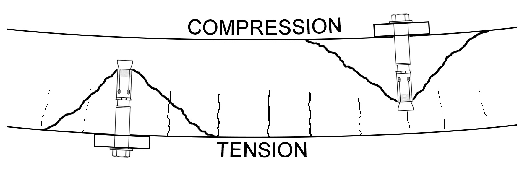
A: The condition of the concrete – cracked or uncracked – has implications on the selection of a suitable fastener as well as fastener design. For the purpose of fastener design, cracked concrete is any concrete whose tensile strength may be exceeded at any time after the fastener has been installed, resulting in a crack that may pass through the plane of the fastener. Cracks may develop due to multiple factors such as the discontinuity introduced due to drilling, hoop stresses developed by the fastener due to installation (e.g. expansion fasteners) and loading, as well as other factors.
Q: How big is a crack in cracked concrete?
A: The definition of cracked concrete is limited to concrete containing crack widths limited to a maximum width equal to 0.3 mm. The prequalification of a fastener for cracked concrete (ETAG 001 Options 1 – 6) requires the fastener to be subjected to a crack movement test comprising 1000 cycles with the crack width ranging from 0.1 – 0.3 mm while a constant tension load is applied to the fastener. At the conclusion of the test the tension capacity of the fastener is determined to ensure it has not been compromised by the presence of the crack. This test is intended to ensure that the fastener performs in a predictable manner in cracked concrete. Details of the prequalification for post-installed fasteners are outlined in ETAG 001. SA TS 101 permits the design of fasteners to cracked concrete only if the fastener has been suitably prequalified (refer to ETAG 001 Part 1, Table 5.3, Options 1 – 6).
Q: How does cracked concrete change the behaviour of a fastener?
A: A fastener may only be used in cracked concrete if it has been prequalified for use in cracked concrete, viz., ETAG 001 Options 1 – 6 for post-installed fasteners. The performance of a fastener in cracked concrete may only be demonstrated through an appropriate testing and assessment program (e.g. ETAG 001).
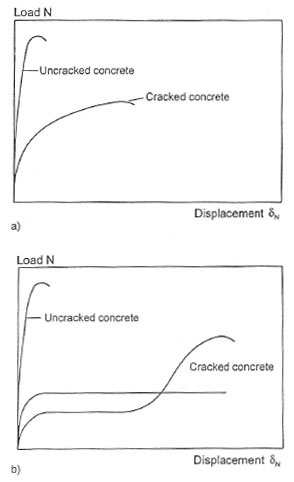
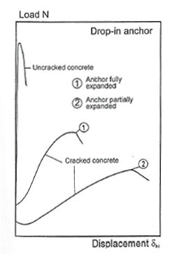
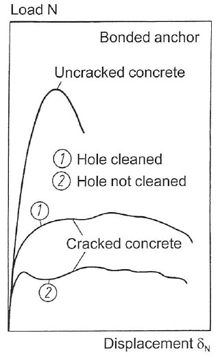
In general, there is a reduction in the strength of a fastener when used in cracked concrete relative to the strength in uncracked concrete. Additionally, there is an expected reduction in stiffness as illustrated schematically in Figure 1.1.
If a fastener that is only prequalified for use in uncracked concrete is used in cracked concrete it may exhibit unpredictable behaviour such as uncontrolled slip or a change of failure mode. Displacement-controlled expansion fasteners (‘drop-in anchors’) are not suitable for use in cracked concrete since they offer no follow-up expansion capacity to remain engaged with the concrete as it separates due to the formation of a crack.
 |
 |
 |
|
||
Q: Can I install a fastener in an existing crack?
A: No. The term ‘cracked concrete’ refers to the condition of the concrete after installation and throughout the fastener’s service life. It does not permit the fastener to be installed in an existing crack. The fastener must be suitably qualified in accordance with SA TS 101 Appendix B in order to be eligible for use in cracked concrete.
Q: Can I install a fastener through cracked concrete and into uncracked concrete and design for uncracked concrete?
A: No. The fastener engages with the concrete to a depth defined by the ‘effective embedment depth’ (hef). If the stress criterion of Equation (3.2) in SA TS 101 demonstrates cracking may develop in the zone where a concrete cone may form, the fastener design must be performed for cracked concrete using a suitably prequalified fastener. Figure 1.2 illustrates how cracks may intersect the formation of a concrete cone.
Q: When do I need to design for cracked concrete?
A: For the purpose of design it should be assumed that the concrete is cracked unless it may be demonstrated via SA TS 101 Equation (3.2) that the combination of stresses in the concrete attributed to extrinsic factors and the stresses in the concrete attributed to intrinsic factors, at any point in time throughout the fastener’s service life, do not exceed the cracking (tensile) strength of the concrete. If the combination of these stresses does not exceed the tensile strength of the concrete throughout the service life of the fastener, the fastening design may be performed for uncracked concrete.
A fastener prequalified for cracked concrete may be used in uncracked concrete. Conversely, a fastener that has a prequalification limited to uncracked concrete may not be used in cracked concrete. The presence of a crack results in a significantly different stress distribution in the concrete (refer to Figure 4.3).
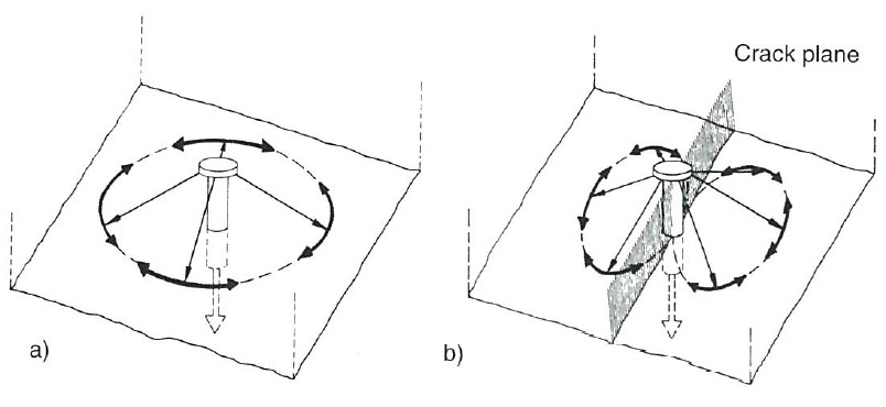
Q: Why is it conservative to adopt f’ct = 0 as the limiting criterion when performing the stress analysis to check for concrete cracking?
A: The conservative assumption to adopt the condition of f’ct = 0 reflects a concrete with zero tensile strength. For example, if the concrete has a characteristic compressive strength (f’c) equal to 32 MPa, according to AS 3600 Cl. 3.1.1.3 the uniaxial tensile strength of concrete (f’ct) is calculated to equal 2 MPa. Depending on the design engineer’s certainty in the assumptions, they may elect to adopt the calculated value of f’ct or assume conservatively, that f’ct = 0.
Q: How do I know if a fastener may be designed for seismic actions?
A: In order to be eligible for applications involving seismic loading a fastener should pass specific testing and assessment requirements. Fasteners used in seismic applications require a more demanding prequalification regime that is above what is required for functioning in cracked concrete under static or quasi-static actions. The European testing and assessment procedure is provided in ETAG 001 Annex E “Assessment of anchors under seismic action”. Design provisions for anchors under seismic loading are not currently provided in SA TS 101, however they are available in EOTA Technical Report 045 (2013). Design guidelines in the US are available in ACI 318 for fasteners meeting the seismic prequalification requirements of ACI 355 for post-installed fasteners or AC 232 for cast-in anchor channel.
Products
Q: Can any anchor to concrete be designed using TS101?
A: No. The scope of SA TS 101 covers mechanical and chemical post-installed anchors as well as cast-in anchor channel. Additionally, in order to be compatible with the design provisions of SA TS 101, the anchors must first be prequalified in accordance with SA TS 101 Appendix B. A specific testing and assessment procedure must be followed in order to develop the appropriate parameters for use in the design equations. Products that have a current European Technical Assessment/Approval (ETA) are compatible with SA TS 101 via minor amendment to notation outlined in SA TS 101 Appendix C.
Q: I want to design a fixing using a fastener that has an ETA and therefore complies with the requirements of SA TS 101 Appendix B. Is there any reason why I cannot specify this fastener?
A: The ETA needs to be relevant to the scope of the intended application.
ETAs are awarded on the basis of satisfying a limited scope of testing and assessment. In the case of post-installed fasteners there are 12 different Options that a fastener may be awarded. The Options related specifically to an intended application for which the fastener is considered to be fit for purpose. The different Options relate to:
- i) Prequalification for cracked or uncracked concrete
- ii) Low or low and high strength concrete
- iii) Single strength for all directions or direction-dependent strength
- iv) Edge or spacing effects present or no spacing and edge effects
- v) Comprehensive or simplified design methodology
In the case of an ETA for anchor channel awarded on the basis of an EAD, it is optional for the anchor channel to be prequalified for fatigue.
Q: Can I use data published by the anchor supplier with the TS101 design procedure?
A: Provided the data has been developed in accordance with the requirements of TS101 Appendix B, the supplier/manufacturer should publish information to this effect. If you are uncertain, contact the technical support of the anchor supplier to seek clarification on whether their product complies with the requirements of SA TS 101 Appendix B.
Q: Can I use products with an ICC approval?
A: Anchor products that have a US prequalification (i.e. ICC approval) are compatible with the design guidelines published in ACI-318. Although the US framework for anchor prequalification and design is similar to SA TS 101, it is not identical. The U.S. ICC approvals are comparable to the prequalification requirements of SA TS 101 Appendix B; however they are not compatible with the parameters and design equations of the SA TS 101 design model. Therefore, these fasteners must be designed according to the ACI 318 design methodology to become a performance solution.
Q: What is the difference between a fastener and an anchor?
A: These two terms are frequently used to describe the same thing: a device connecting an element to concrete. In Australian practice a fastener installed in concrete may be referred to as an ‘anchor’, such as ‘mechanical anchor’ and ‘chemical anchor’.
Design
Q: Which modes of failure need to be considered during design?
A: There are many different modes of failure needing to be considered during design, depending on the type of anchor, the loading conditions, characteristics of the substrate and details of the installation. Some modes of failure originate in the fastener, some originate in the substrate, others depend on the fastener-substrate interaction. The mode of failure may change as the characteristics of installation and substrate change.
Full details of the modes of failure requiring verification for post-installed and cast-in fasteners are provided in SA TS 101 Clause 3.4.
Q: Manual design is cumbersome and time-consuming. Is there an easier way?
A: Yes – software. The design for a single anchor may take a considerable amount of time owing to the different modes of failure needing to be considered and the complexity of the design methodology. Fortunately, most reputable anchor suppliers provide suitable software that is available for download free of charge. Most software packages will generate a comprehensive report that details the calculation for strength. TS101 is based on the European design methodology. For further guidance on how to use anchor design software, contact the technical support from your preferred supplier.
Q: Can SA TS 101 be used to calculate development length and stress in reinforcement?
A: AS 3600:2009 Section 13 provides the design method for calculating stress development in (cast-in) reinforcement. The design procedure provided in SA TS 101:2015 is restricted to design for shallow anchorage (hef < 20dnom) failure involving concrete modes of failure and steel fracture. The design methodology is not applicable to the calculation of stress development in the metal component (reinforcement). The design is limited by data published by the anchor manufacturer in accordance with SA TS 101:2015.
Q: How does the depth of the concrete element influence splitting failure due to loading?
A: Provided the depth of the concrete member is greater than a minimum value (hmin) and the corresponding edge distance of the fastener is not less than the characteristic edge distance for splitting failure (ccr,sp) splitting failure will not occur due to loading. The combination hmin and ccr,sp for a characteristic tension load are determined during the fastener’s prequalification. If either hmin or ccr,sp are reduced splitting failure may occur.
One method (SA TS 101:2015 Clause 6.2.5.2 (a)) to avoid splitting due to loading is to ensure both the following conditions are met:
- The depth of the concrete member is no less than the minimum concrete member depth (h > hmin) prescribed in the product’s prequalification and either, and
- Edge distance in all directions is greater than the characteristic edge distance for splitting failure (c > ccr,sp for single fasteners, c > 1.2ccr,sp for fastener groups)
ETAG 001 Clause 7.1 ‘Design methods for anchorages’ states the following:
“If the minimum member thickness is smaller than 2hef the characteristic resistance of the anchor shall be evaluated from tests with single anchors at the corner and the member thickness chosen (Part 1, Table 5.4 line 14). This characteristic resistance is valid for member thickness hmin < h < 2hef.”
Q: TS101 does not cover design for fire. Where can I find guidance on design for exposure to fire?
A: AEFAC recommends you seek guidance from your supplier’s technical support to assist you in developing solutions for applications requiring design for exposure to fire. Guidance may also be found in the upcoming publication EN 1992-4 which is scheduled for publication at the end of 2016/beginning of 2017.
Q: SA TS 101 does not cover design for durability. Where can I find guidance on design for durability?
A: At present the best source of information on durability considerations for fastening design is via technical support provided by the fastener manufacturer/supplier.
Q: SA TS 101 does not cover anchor design for seismic actions. Where can I find guidance on design for seismic actions?
A: In order to be eligible for use in seismic applications and anchor should be suitably qualified. The European procedure for the testing and assessment of anchors to seismic actions is covered in ETAG 001 Annex E. Consult your supplier for evidence of suitability.
Q: Where can I find guidance for applications not covered by SA TS 101?
A: For applications not covered under the scope of SA TS 101:2015, additional guidance specific to the design of fasteners in concrete may be found in the following references:
- Design for durability: EN 1992-4 “Eurocode 2: Design of concrete structures – Part 4: Design of fastenings for use in concrete” (awaiting publication, pre-standard guidelines available in prEN 1992-4)
- Design for exposure to fire: EOTA Technical Report 020 “Evaluation of anchorages in concrete concerning resistance to fire”
- Design for seismic actions: EOTA Technical Report 045 “Design of metal anchors for use in concrete under seismic actions”
- Design for fatigue: EN 1992-4 “Eurocode 2: Design of concrete structures – Part 4: Design of fastenings for use in concrete” (awaiting publication, pre-standard guidelines available in prEN 1992-4)
- Reinforcing bar – design for development length: AS 3600 “Concrete structures”, EOTA Technical Report 023 “Assessment of post-installed rebar connections”
- Fasteners for lifting, transport and erection: AS 3850.1:2015 “Prefabricated concrete elements – Part 1: General requirements”
Q: When designing a fixture containing multiple fasteners, which fastener should I design for?
A: In the case of a fixture containing multiple post-installed fasteners the most unfavourable fastener is determined according to the load on the fastener and the available resistance depending on edge distance and spacing. All fastenings in a fixture should be of the same type in order to avoid a fastener attracting a greater proportion of the load due to a relatively greater stiffness compared with other fasteners in the fixing.
Q: How do I ensure the correct product is installed on site?
A: It is imperative the fastener installed on site is the same as the fastener designed for. Different fasteners that have similar geometry, may look similar, and may even be from the same manufacturer can have very different performance characteristics. It is dangerous to substitute products without the approval of the responsible engineer.
In order to ensure the correct product is installed, ensure a complete and accurate fastener specification is provided on the construction drawings. Recommendations for the information to be included on construction drawings for fastenings to concrete are provided in the AEFAC Technical Note “Guideline for the specification of fastenings to concrete – engineering general notes” that is freely available from the resources page.
Q: How do I calculate the Working Load Limit (WLL) using SA TS 101?
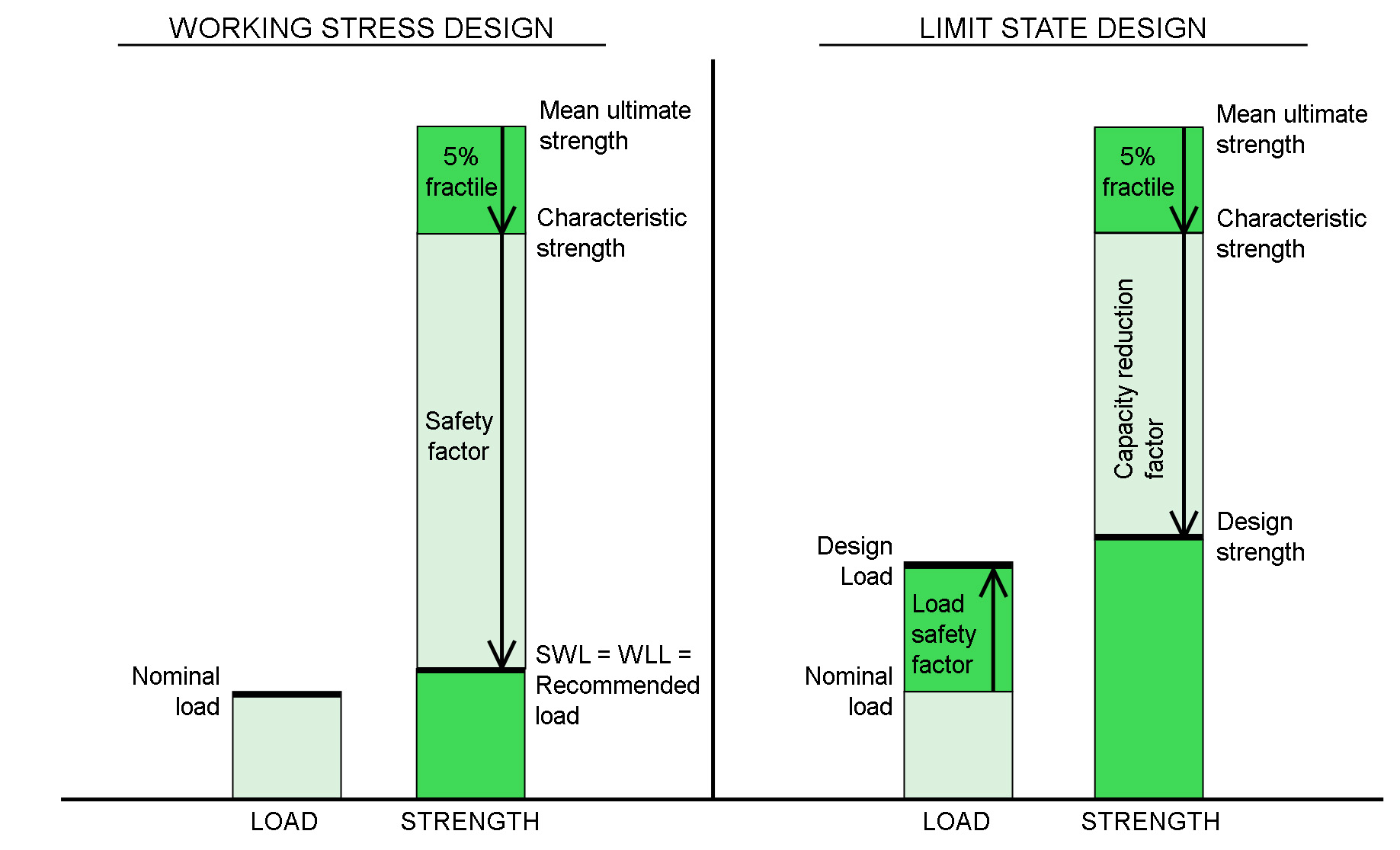
A: Working Stress Design (WSD) is a method of proportioning structural members and connections, such that elastically computed stresses produced in the members by nominal loads do not exceed specified allowable stresses. A factor of safety is used to account for uncertainties and ensures the structure remains well within the elastic range. The method has many limitations and has been superseded by the more rational and accurate reliability-based Limit State Design methodology. An illustration of the two methods is provided in Figure 4. The WSD method assumes any variability in the loading or strength is the same for different design scenarios.
Using the WSD method the Working Load Limit (WLL) may be calculated as follows:

Q: How can edge reinforcement be accounted for in the design of cast-in channel?
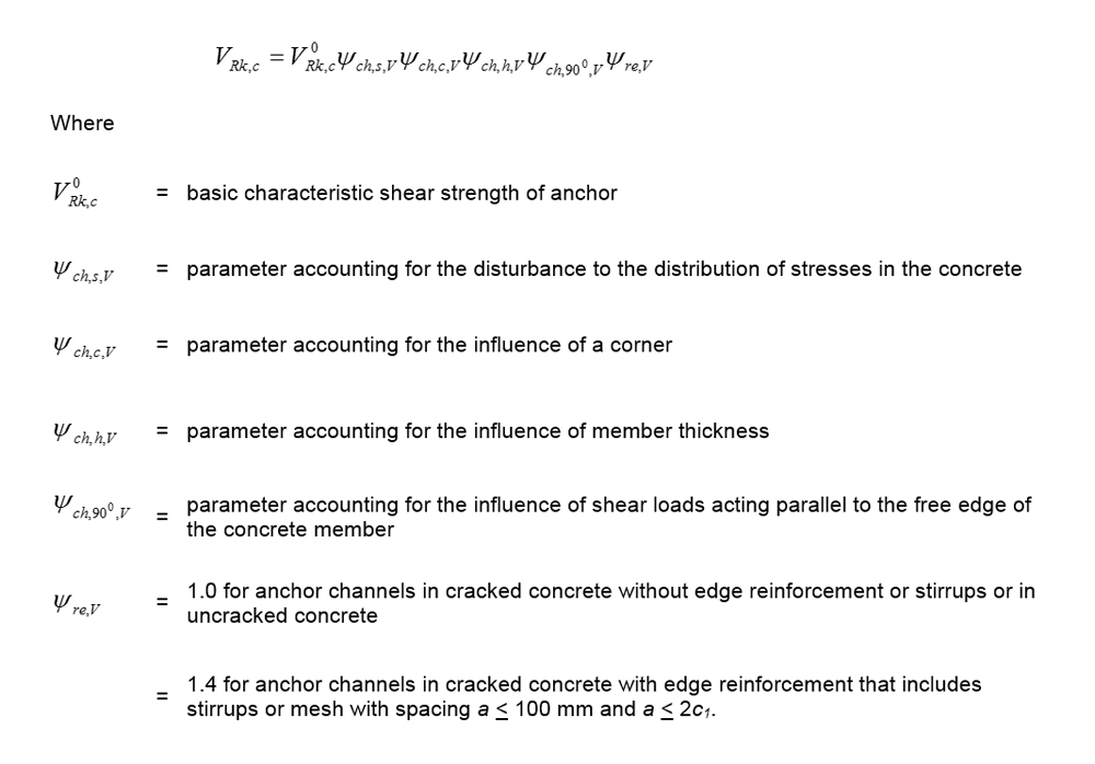
A: The calculation for strength against concrete edge failure (VRk,c) for cast-in anchor channel that is given in SA TS 101:2015 does not account for the contribution of supplementary reinforcement. In order to account for the contribution of supplementary reinforcement in the calculation of the concrete edge failure mode, an additional parameter accounting for edge reinforcement (ψre,V) is introduced to a revised calculation for the strength against concrete edge failure as follows:
Installation
Q: How do I make sure the anchor is installed correctly on site as per the design?
A: Correct installation is imperative to ensure the designer’s intent is met. In order to ensure correct installation the following two steps are required:
1. Ensure an accurate and complete specification is provided. Recommendations are provided in the AEFAC Technical Document “Guideline for the specification of fastenings to concrete - engineering general notes” on the resources page.
2. SA TS 101 Appendix C Clause C.1 recommends the installer is competent and suitably qualified through the AEFAC Installer Certification Program and/or a specific training program from the product supplier. For further information on the AEFAC Installer Certification Program refer to the certification page.
Installation of fasteners by personnel not suitably competent may jeopardise the safety of the project.
Q: What information do I need to include on the specification?
A: The information required on a specification should ensure the following:
i) The installer is sufficiently qualified to perform the installation.
ii) Sufficient information that will enable the contractor to select the correct tools and to install the anchor as per the design.
iii) Sufficient detail is provided to ensure that it is not possible to procure an unsuitable product.
Details of sample specifications may be found on the resources page.
References
- AEFAC Technical Note “Guideline for the specification of fastenings to concrete – engineering general notes” www.aefac.org.au/resources.php
- AS 3600:2009 “Concrete structures”, Standards Australia
- AS 3850.1:2015 “Prefabricated concrete elements – Part 1: General requirements”, Standards Australia
- Eligehausen, R., Mallee, R. and Silva, J. F., 2006, “Anchorage in Concrete Construction”, Ernst & Sohn, Berlin, Germany
ETAG 001 Part 1 “Guideline for European Technical Approval of metal anchors for use in concrete – Part one: anchors in general”, European Organisation for Technical Assessment, www.eota.eu - ETAG 001 Part 2 “Guideline for European Technical Approval of metal anchors for use in concrete – Part two: torque-controlled expansion anchors”, European Organisation for Technical Assessment, www.eota.eu
- ETAG 001 Part 1 “Guideline for European Technical Approval of metal anchors for use in concrete – Part three: undercut anchors”, European Organisation for Technical Assessment, www.eota.eu
- ETAG 001 Part 1 “Guideline for European Technical Approval of metal anchors for use in concrete – Part four: deformation-controlled expansion anchors”, European Organisation for Technical Assessment, www.eota.eu
- ETAG 001 Part 1 “Guideline for European Technical Approval of metal anchors for use in concrete – Part five: bonded anchors”, European Organisation for Technical Assessment, www.eota.eu
- ETAG 001 Part 1 “Guideline for European Technical Approval of metal anchors for use in concrete – Part six: anchors for multiple use for non-structural applications”, European Organisation for Technical Assessment, www.eota.eu
- ETAG 001 Part 1 “Guideline for European Technical Approval of metal anchors for use in concrete – Annex A: details of test”, European Organisation for Technical Assessment, www.eota.eu
- ETAG 001 Part 1 “Guideline for European Technical Approval of metal anchors for use in concrete – Annex B: tests for admissible service conditions detailed information”, European Organisation for Technical Assessment, www.eota.eu
- ETAG 001 Part 1 “Guideline for European Technical Approval of metal anchors for use in concrete – Annex E: assessment of metal anchors under seismic action”, European Organisation for Technical Assessment, www.eota.eu
- NCC, 2016, “National Construction Code”, Australian Building Codes Board, http://www.abcb.gov.au/Resources/Publications/NCC/NCC-2016-Complete-Series
- prEN 1992-4:2013 “Eurocode 2: Design of concrete structures – Part 4: Design of fastenings for use in concrete” (pre-standard for public comment), CEN-CENELEC
- SA TS 101:2015 “Design of post-installed and cast-in fastenings for use in concrete”, Standards Australia
- Senate Interim Report, 2016, “Non-conforming building products, Interim report”, The Senate, Senate Printing Unit, Parliament House, Canberra, www.aph.gov.au
- Technical Report 020 “Evaluation of anchorages in concrete concerning resistance to fire”, European Organisation for Technical Assessment, www.eota.eu
- Technical Report 023 “Assessment of post-installed rebar connections”, European Organisation for Technical Assessment, www.eota.eu
- Technical Report 045 “Design of metal anchors for use in concrete under seismic actions”, European Organisation for Technical Assessment, www.eota.eu
